Never done this, let’s try it!
PCB Requirements
- 2s Li-Ion power (5,4 – 8,4V) via battery holder
- reverse polarity protection
- up to 6s external power (5,4 – 28V) via XT60 connector
- mechanical power switch
- 1-3 push buttons
- USB-C connector for flashing (no power)
- 5V 4A rail for LEDs
- 3,3V 1A rail for MCU
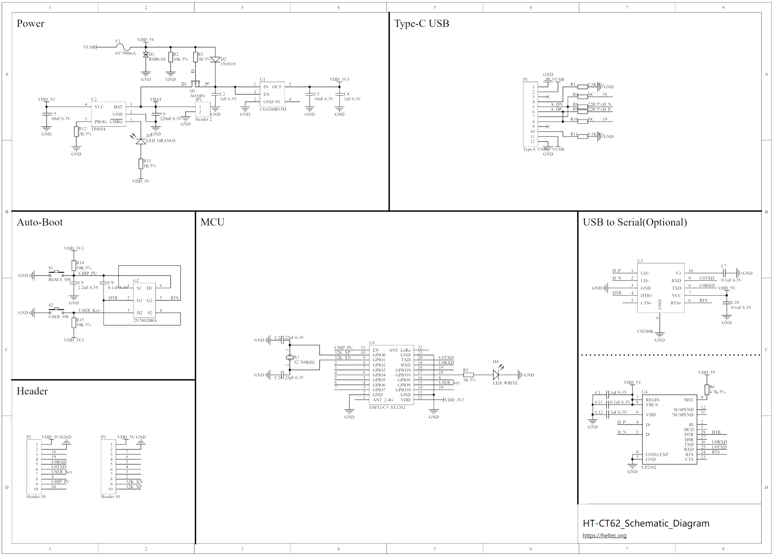
- footprint for Heltec HT-CT62 module
- optional: PWM LED output for up to 3-4 channels
I know two free software tools for designing a PCB: KiCAD and EasyEDA. Because the second option is web-based I opted for that.